So, here is the guide of making this plane, so let’s see what we need beforehand.
- Fusion Files: Drive Download Link
- Carbon Fiber (CF) rods: 1.5mm, 2mm, 3mm and 5mm
- M2 nuts and bolts: optional
So yeah, that is all, First start with the main frame i.e. fuselage (F1, F2, F3 and F4) (fig 1). The information about what electronics will go where is given in the fusion files in electronics folder (fig 2) and in that gyro is optional and not necessary. All main frame parts can be attached by m2 nuts and bolts and the removable glue such as fevicol should be applied to strengthen the bond. In F2 the battery holder’s front part that is covering the part (fig 3) should be cut by a heated knife or a plyer. Its there just to get rid of 3d printing supports and to get get a cleaner print.
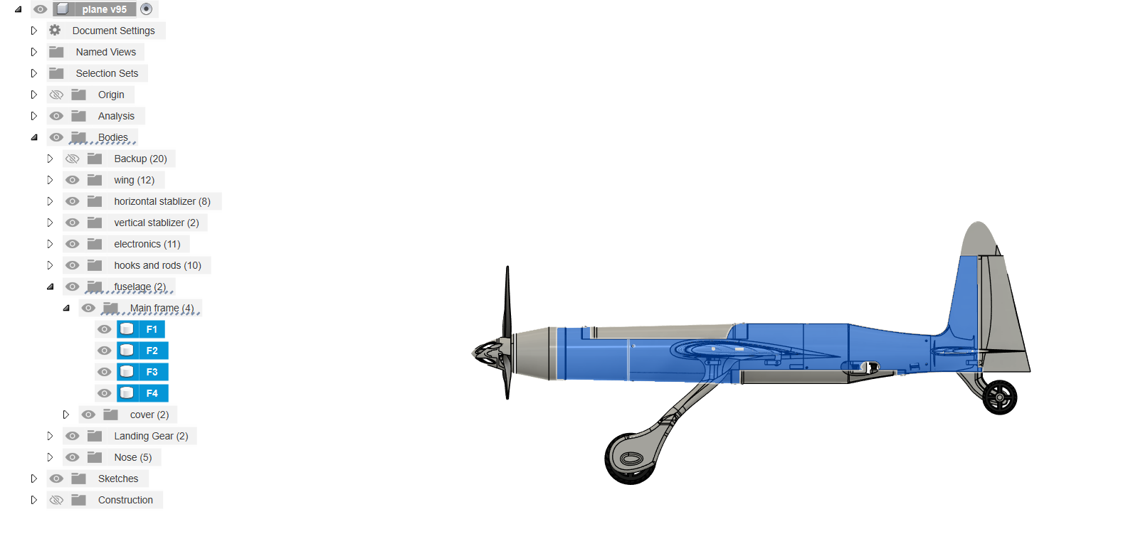
fig 1 - main frame parts
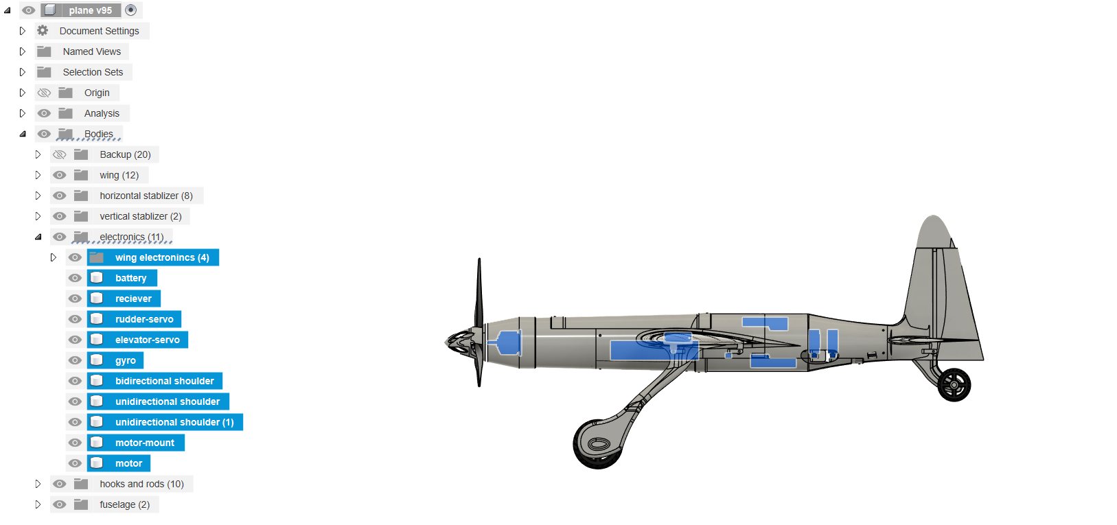
fig 2 - electronics location
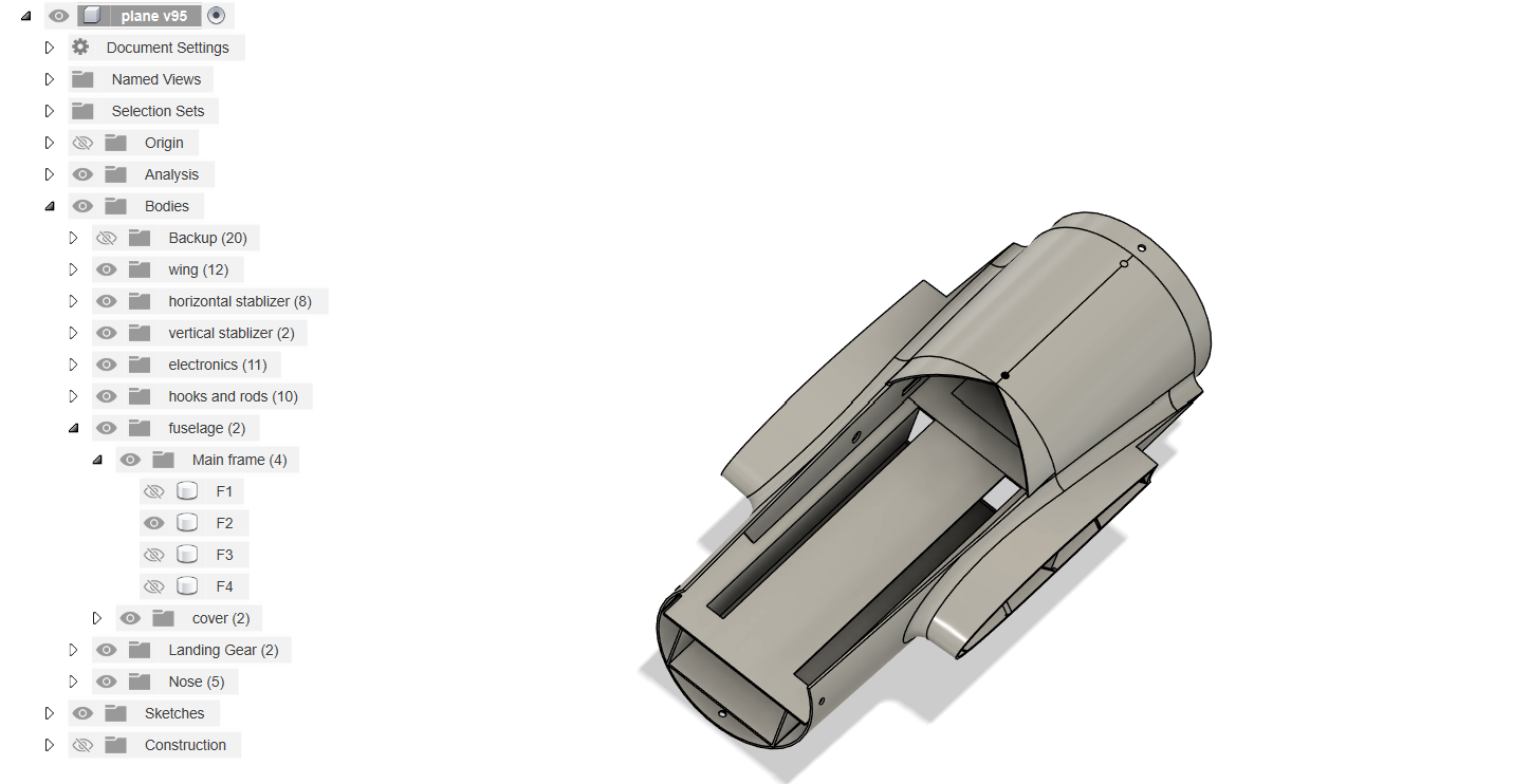
fig 3 - main frame's F2 Battery holder parts that needs to be removed
Then we will print our wings, start with w1-L, w2-L and w3-L and w1-R, w2-R and w3-R and then print the aileron parts, the gap in w1-L and w1-R is given for servo motors (fig 4). Insert the 5mm CF rod from left wing to right wing. Then print the vertical and horizontal stabilizers. All the different parts can be joined by CA (Cyano-Acrylate) glue. There is slot for 1.5 mm CF rods in ailerons to attach it to the wings and the main frame. 2 or 3mm CF rods can be inserted to in horizontal stabilizer and 1.5 mm CF can be inserted in vertical stabilizer. The hooks can be joined together by a 1.5mm CF rod that will function as push rod.
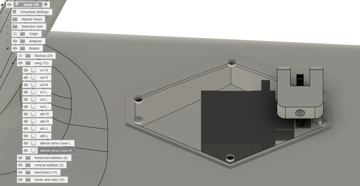
fig 4 - Servo holder in w1-R wing part
Then we will print the hooks that are to be joined in the specified place given in fusion files. Then you can start printing the back landing gear, the design is straight forward, you will need to insert 3mm CF rod to insert in that. Then you can print the front landing gear parts and then join them with CA glue, you can also give them a little heat treatment for strength. Then you can print the nose of the plane, In my opinion you should use tri blade propeller instead of bi blade. And yeah, now you have your own UAV styled spitfire, you can modify as you want and you also insert a little camera in the bottom of the main frame.
Image Gallery
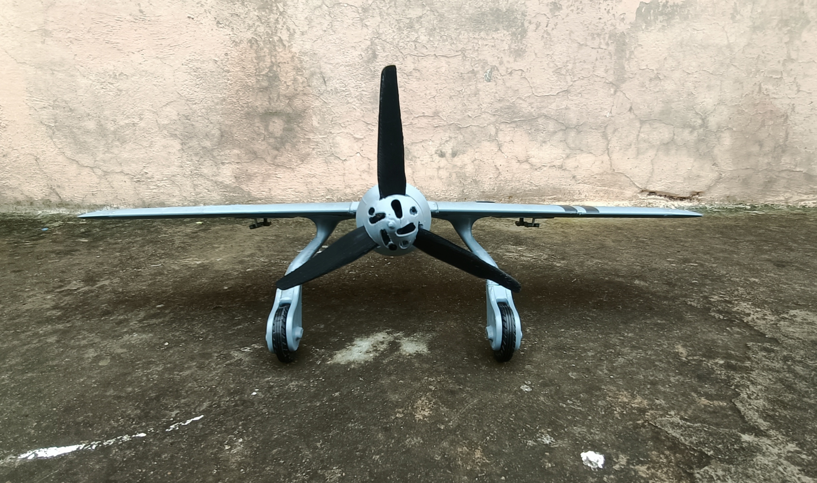
fig 5 - front photo of final result (3d printed plane)
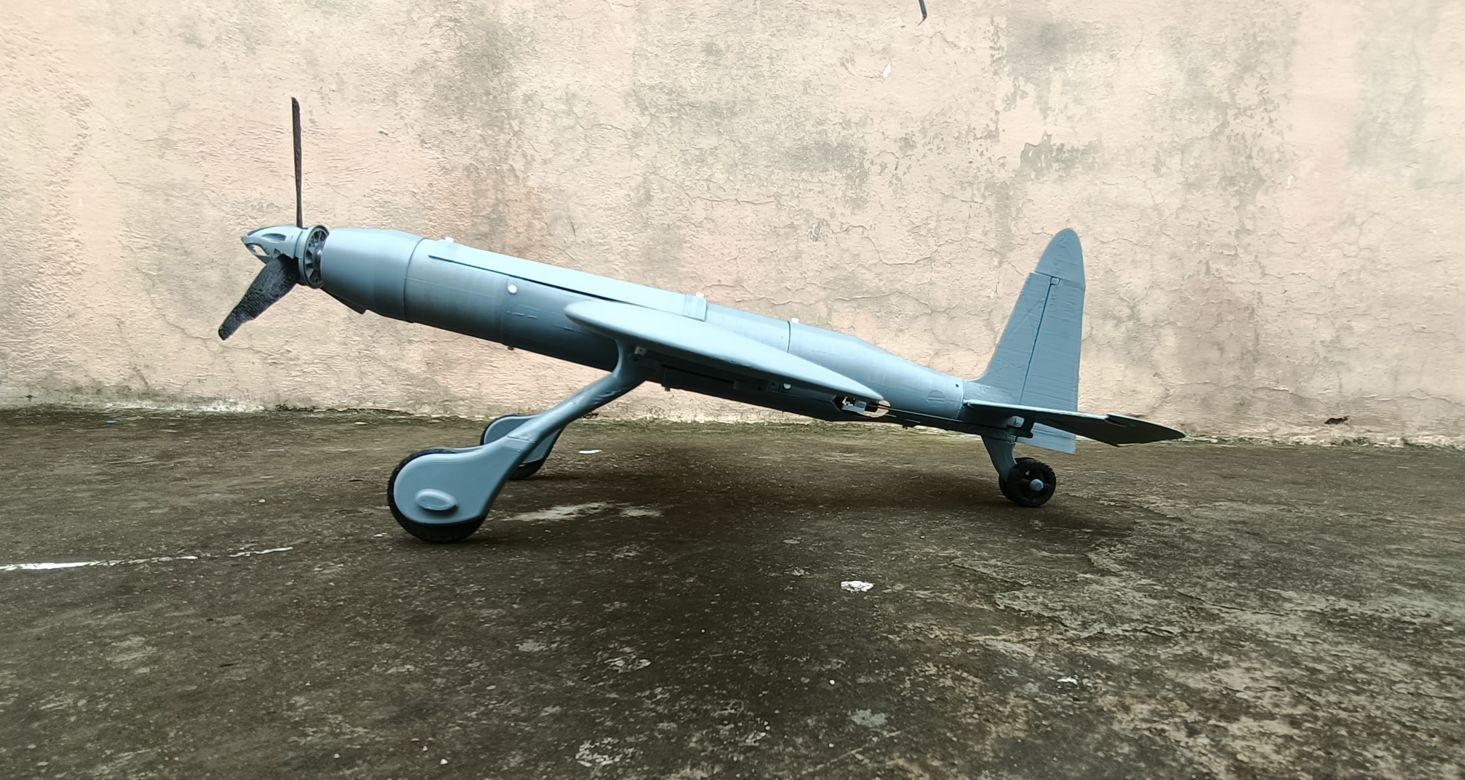
fig 6 - side photo of final result (3d printed plane)
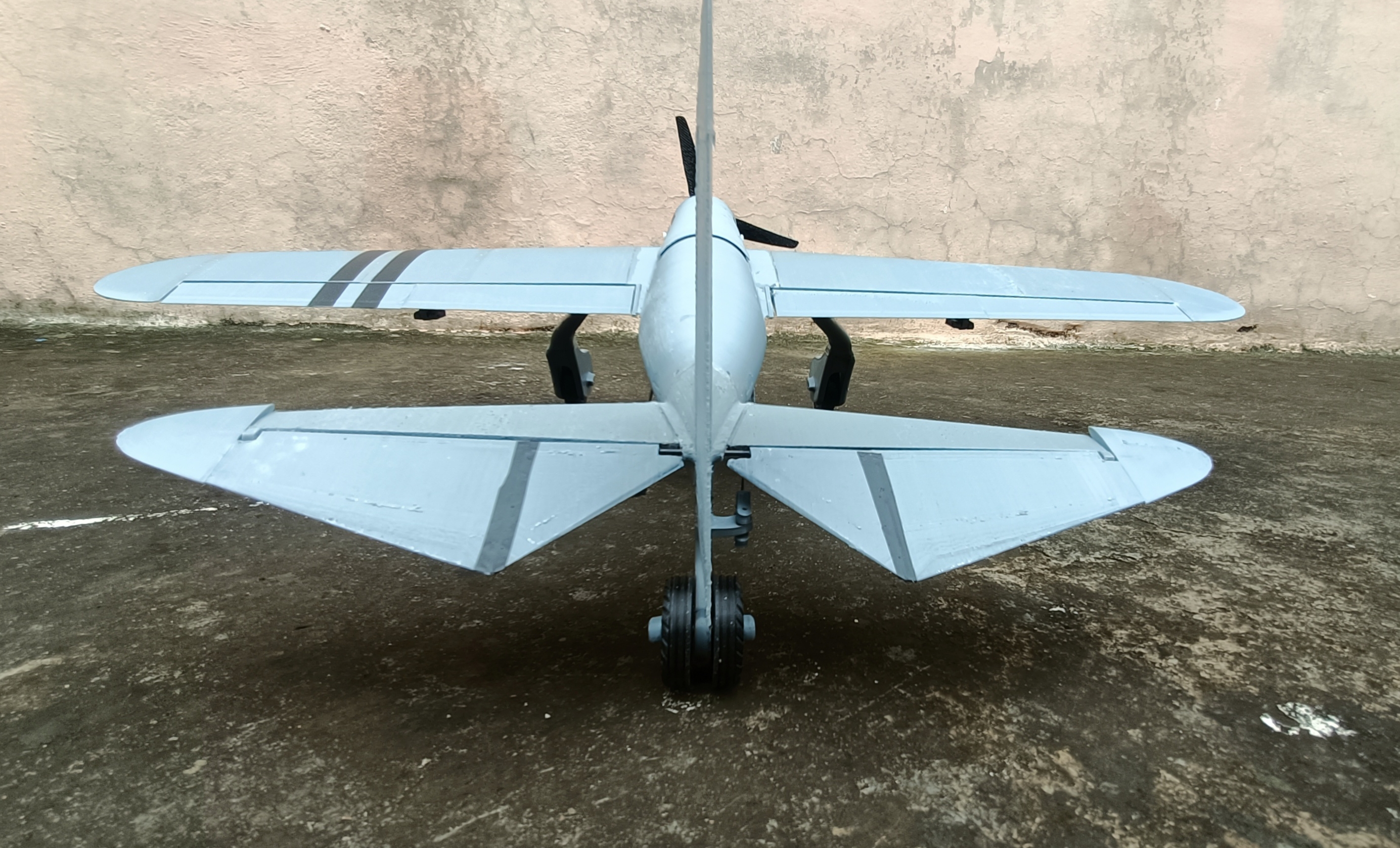
fig 7 - back photo of final result (3d printed plane)
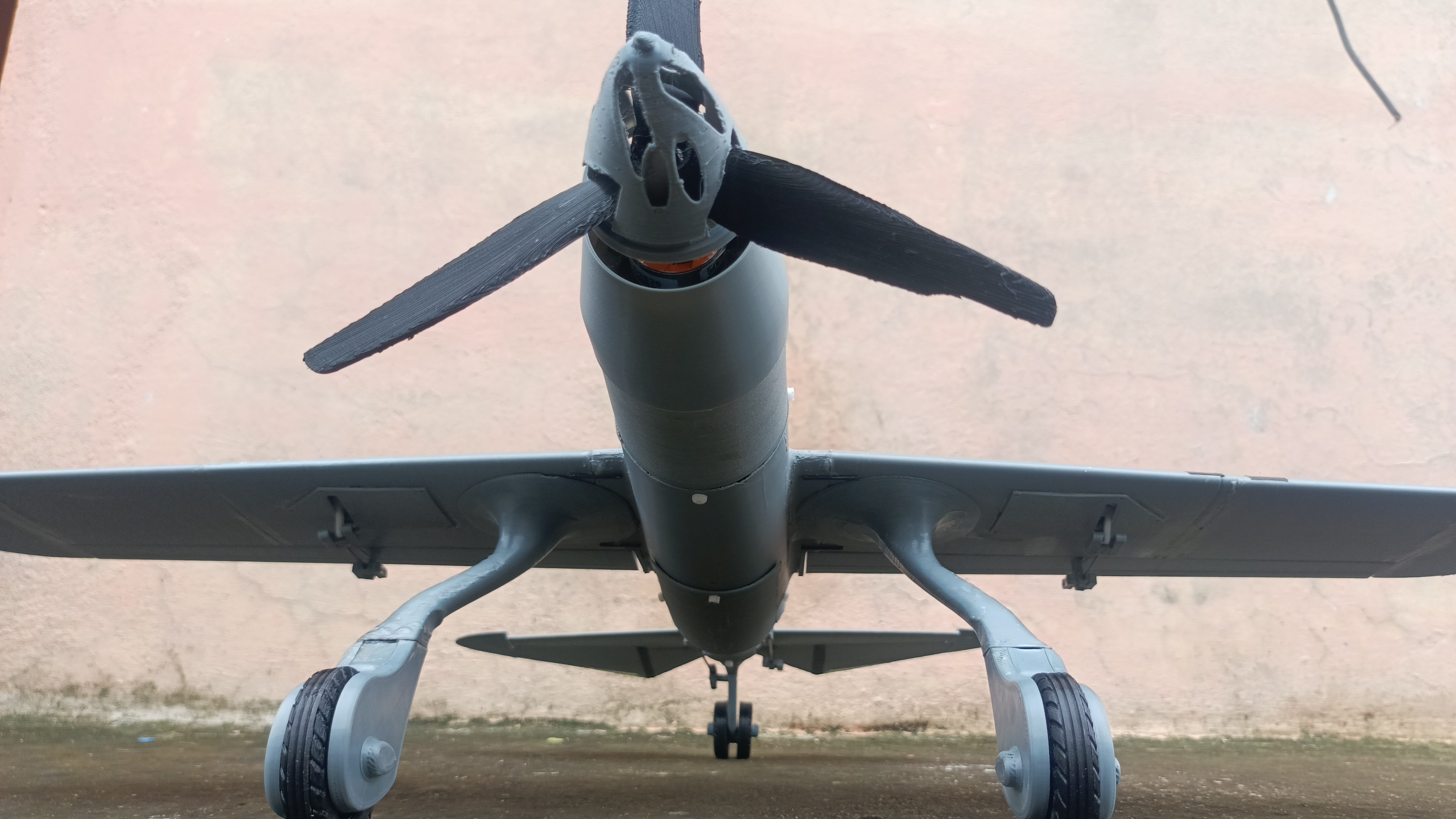
fig 7 - front-bottom photo of final result (3d printed plane)